Adding a Micro SD slot to the NTC CHIP(转载)
Adding a Micro SD slot to the NTC CHIP
Publish date: 2019-04-21
Tags: ntc-chip, ARM, SBC, Linux, hardware
In the previous post, I explained why the NAND storage included with the NTC CHIP is problematic. The main reason is of course that it isn’t supported by the mainline Linux kernel and U-Boot. Even if patched back in, it isn’t particularly reliable and is also much slower and smaller than current SD cards. Fortunately, the Allwinner A13/R8 SoC includes an SD card controller and NTC brought the necessary I/O pins out to the headers from the SoC which means we can add our own slot relatively easily!
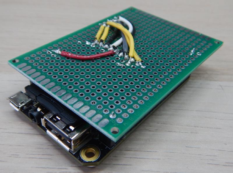
Micro SD slot ‘hat’ for CHIP
One issue with this build is that it won’t work as described if you are using the CHIP in the PocketCHIP case. I generally use mine as standalone devices in various projects, such as running the OctoPrint print server for my 3d printer.
Before the demise of NTC, it looks like someone made a very nice product that was able to be installed between the CHIP and PocketCHIP case allowing one to add an SD card to the PocketCHIP called the Tzatziffy II. Unfortunately it looks like it’s been sold out for a while and probably won’t be produced again. The design is available as a github repository, so someone could theoretically get enough people together to make another production run worthwhile if there is enough interest. The original creator should be contacted both out of respect and also because I couldn’t actually find a license file in the project with a quick skim through. They also might be able to do a production run the easiest if enough orders were lined up.
This build will require soldering skills but it’s not too difficult. I will admit I’ve been soldering things for a long time including quite a bit of board assembly at my first job out of college. I made mine with the $4 cheap-o soldering iron from Harbor Freight but a better iron will make it significantly easier. The most important thing is to use soldering flux! While leaving you with a bit of a mess to clean up, this makes pretty much any soldering job much easier. Because the SD card adapter is made of plastic, you want to be fast with your work so you don’t melt it and the flux will allow the solder to bond with the pads much more quickly. If you’re like me though, you probably have a bunch of these adapters lying around so you can probably take a few tries to get it right.
Parts
This project can be done with as little as a soldering iron, solder, an SD card adapter, and some wires. In fact, this is how I did it the first time because I had everything on hand and wasn’t sure it would work at all.
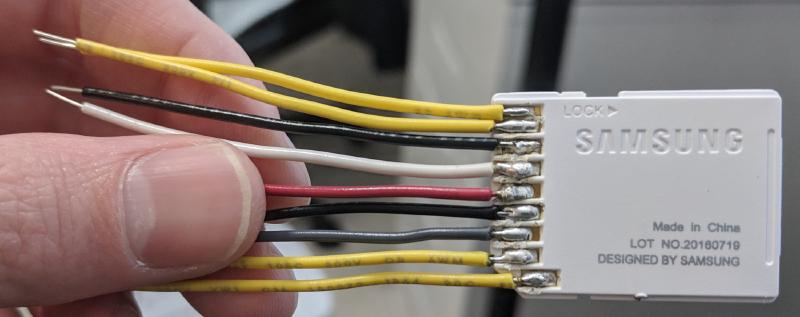
Wires soldered directly to SD Adapter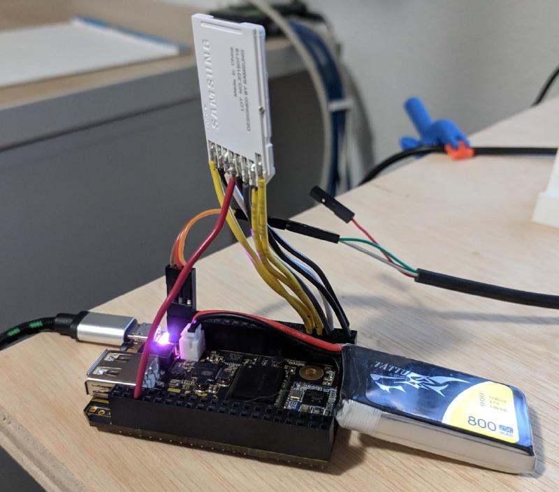
Ugly and cumbersome, but functional
I would recommend the following to make a nice finished project as well as making it much easier on yourself. For convenience, I’ve included links to Amazon with my Amazon Associate ID, from which I can earn a little bit for qualifying purchases. A lot of this stuff is common though and you probably have or can borrow some of it, or find it around town except for perhaps the perfboard and pin headers. Most of the stuff I have on hand anyway for various projects, so this project essentially cost me nothing but time. If you have a maker space in your town, they should have a lot of this stuff too, especially the tools.
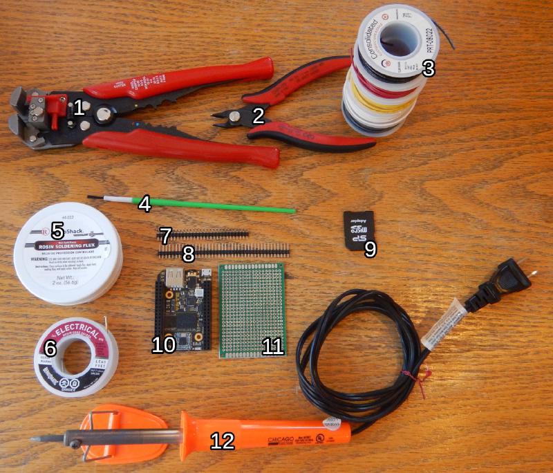
Parts and tools used to make a Micro SD card slot for your CHIP
No. Part Notes
1 Wire Strippers I really like these self-adjusting wire strippers but anything that strips insulation from wire will do just fine.
2 Flush Cutters Very useful tool to have on hand for tons of situations. I have a bunch of these.
3 Solid Wire Nice to have in several colors for color coding.
4 Brush Useful for applying flux and cleaning it up with alcohol when finished. I got a pack of cheap ones at Harbor Freight.
5 Rosin Flux If you’re having trouble soldering, more flux is usually the answer.
6 Solder Rosin core solder. Even though the solder already has flux, more still makes the job easier.
7 Right Angle Pin Header Attaches to SD card adapter.
8 Pin Header Attaches to perfboard so it can plug into CHIP. Available in a kit with right angle and others linked above.
9 SD Adapter Usually included with your Micro SD card.
10 NTC CHIP You should have this already.
11 Perfboard Great for all kinds of projects. This one is double sided and comes tinned making it easy to work with.
12 Soldering Iron Cheapo soldering iron. You should get a better one if you do this a lot. A cheap handle is fine but quality tips are worth the money. Something like the one I linked should take 900M style tips from a quality brand like Hakko. I’m using a cheap $4 iron from Harbor Freight to show it can work for you though.
I drew some crude wiring diagrams for both the Alpha CHIP and the released version because they moved the 3V3 power supply location. You most likely have the non-Alpha version. The normal CHIP has the pin function conveniently written onto the header so it should be easy.
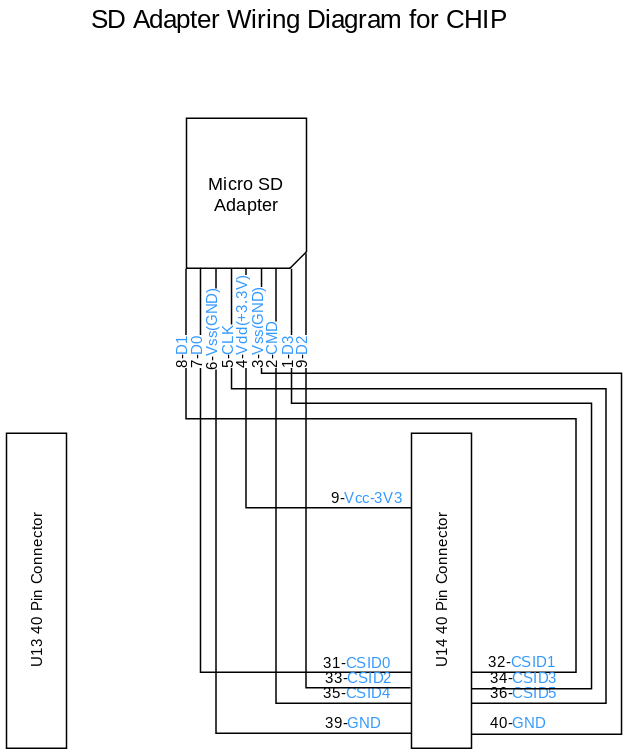
Wiring diagram for released CHIP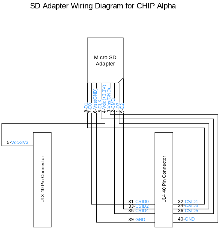
Wiring Diagram for Alpha version of the NTC CHIP
The assembly is actually fairly straightforward. Headers can be clipped apart with the flush cutters. You need to attach the longer pins of the right andgle header to the Micro SD adapter’s exposed pads. It won’t line up exactly, but it’s close enough and far easier than trying to solder on individual wires. I’d recommend a fairly large soldering tip as that will allow you to dump heat into the joint very quickly. It probably seems a bit counter intuitive, but this is what you want so you can make the solder flow and adhere well onto the pad and the pin before the heat has enough time to transfer to the surrounding area and melt the plastic. Use plenty of flux on both the adpater pads and the header pins and you should be able to get the solder to flow onto both quickly. One that is done, it can easily attach to the perfboard.
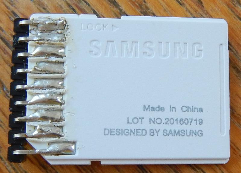
SD Adapter with right angle pin header soldered onto its pads
Next, you should attach some of the straight pin headers to the perfboard so that they line up with the holes on the CHIP’s headers. The short end should go to the perfboard so that the longer end can stick down into the CHIP. I found it easiest to actually stick the long end of the header into its spot on the chip, then set the perfboard on top how you want it and solder the pins in place.
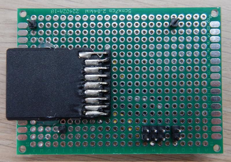
Pin headers attached to perfboard
Next, you’ll need to solder wires to connect the pins from the SD Card adapter to the approriate pin on the CHIP connector. I prefer to color code mine but it doesn’t matter if you want to just use a single color. There’s probably enough solder already on the joint between the header and the perfboard to connect the wire, but feel free to add more. It’s easier to make the connection if you dip the end of the wire in some flux and tin it, that is coat it in solder on its own. It should be fairly straightforward, but be careful not to bridge any pins or short any wires together, especially on the group of six CSI pins where it gets a bit tight.
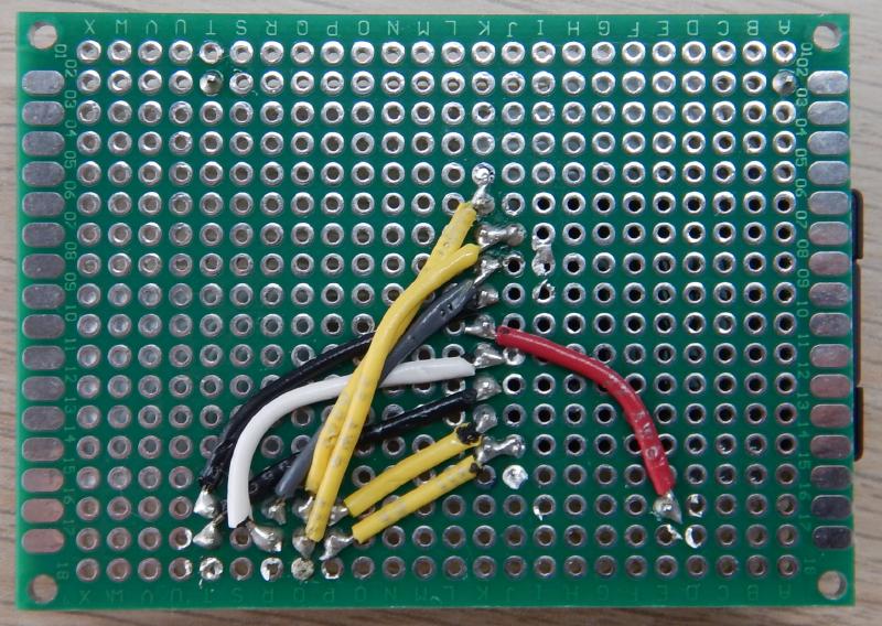
Wires connecting SD adapter header to CHIP headers
When you’re done you may want to take a multimeter in continuity mode (beeps when the probes complete a circuit) and double check that the connections you want to be there are there and also that they don’t short out with each other. This is a pretty simple circuit so a visual inspection can go a long way also. I also added some hotglue to reinforce the adapter connection to relieve stress placed on the header when manipulating the card.

Hot glue for stress relief
Wrapping Up
Put away your tools, that’s it for the hardware part of this project! In the next post I’ll explain how to get this to work in Linux. We need to add some information to the device tree so that Linux knows how to configure the appropriate driver and then you’ll be able to use your SD card slot. Overlaying the device tree will work on the stock NTC kernel, so if all you wanted was an SD card slot, you’re almost done.