2021年8月

Publish date: 2019-05-16
Tags: ntc-chip, ARM, SBC, Linux, hardware
Now that you have the Micro SD hat hardware, you need a way to tell the kernel about it so it can load the drivers and interface with it. On an ARM based machine, this is done with a data structure called the device tree. The device tree is like a giant config file that tells the kernel all about the hardware that exists in the machine. It contains things like what type of device something is, what address it’s mapped to in memory, what I/O pins it uses, and things like that.

The device tree is a hierarchical structure compiled into a binary format and passed into the kernel at boot time by the bootloader (U-Boot). It would be a bit of a hassle if we had to make our changes, recompile this file, flash it to the CHIP, and then have U-Boot pass in the new device tree. Fortunately, since we don’t need the Micro SD card reader to boot the stock NTC kernel, we can describe it in its own small file, compile that fragment, and apply it as an overlay to the device tree after the machine has booted up.

Summary
This post describes how to build the overlay if you want to do it yourself from scratch. If you don’t care about that and just want the overlay, you may enter these commands into the shell to install it yourself from the archive I have provided. These steps will download the archive, extract it, copy files to necessary locations, and then enable application of the overlay when the system starts.

cd ~
curl -LO https://byteporter.com/mmc-overlay-for-ntc-kernel/mmc2-4.4.13-ntc-mlc.tar.gz
tar xfvz mmc2-4.4.13-ntc-mlc.tar.gz
sudo mkdir /lib/firmware/overlays
sudo cp mmc2-4.4.13-ntc-mlc/mmc2-ntc.dtbo /lib/firmware/overlays/
sudo cp mmc2-4.4.13-ntc-mlc/mmc2-overlay.service /etc/systemd/system/
sudo systemctl daemon-reload
sudo systemctl enable mmc2-overlay

You may now either reboot and the mmc2 overlay should be applied on startup, or you can start the service to apply the overlay without restarting by issuing the command sudo systemctl start mmc2-overlay. After rebooting or issuing that command, you can check its status with the command systemctl status mmc2-overlay.

Describing the hardware
To describe the hardware, you could look everything up in the data sheet provided by the manufacturer. While this is a great option as a last resort, thankfully most of this work has already been done and included in the source code for the Linux kernel for a vast array of single board computers, including the CHIP. They’ve organized their source files well and provide several header files with definitions that we can make use of. We could of course just hard code the numeric values that we look up from the data sheet, but this is a poor practice because it will be hard to understand when reading it later what those values are meant to indicate.

We want to enable the SD Controller 2 peripheral on the Allwinner SoC. We’ll tell it to use the pins on Port E because that’s what we wired up. The drive current will be 30 mA and pull function should be set to pull up. Bus width is 4 bits and the power is supplied by the 3.3V regulated supply from the PMIC. Clocks come from the data sheet and are already defined for us in the included files.

A normal SD slot has a small switch inside that the controller can use to detect when a card is inserted. Our SD Adapter kludge does not have that functionality though, so we need to specify broken-cd, which will tell the driver to simply poll for an SD card. In my experience, this works just fine and seems to cost negligible computing resources.

To enable the driver, set status = "okay". That should be it! Here’s our completed overlay source:

/dts-v1/;
/plugin/;

#include <dt-bindings/pinctrl/sun4i-a10.h>
#include <dt-bindings/gpio/gpio.h>
#include <dt-bindings/input/input.h>
#include <dt-bindings/interrupt-controller/irq.h>

/ {
    compatible = "nextthing,chip", "allwinner,sun5i-r8";
    
    /*      Enable our SDIO pins         */
    fragment@0 {
        target = <&pio>;        
        __overlay__ {

            chip_sdio_pins: mmc2@42 {
                allwinner,pins = "PE4", "PE5", "PE6", "PE7", "PE8", "PE9";
                allwinner,function = "mmc2";
                allwinner,drive = <SUN4I_PINCTRL_30_MA>;
                allwinner,pull = <SUN4I_PINCTRL_PULL_UP>;
            };
        };
    };


    /*     Enable our SDIO device     */
    fragment@1 {
        target = <&mmc2 >;

        __overlay__ {
            vmmc-supply = <&reg_vcc3v3>;
            vqmmc-supply = <&reg_vcc3v3>;

            pinctrl-names = "default";
            compatible = "allwinner,sun5i-a13-mmc";
            pinctrl-0 = <&chip_sdio_pins>;

            bus-width = <4>;
      clocks = <&ahb_gates 10>,<&mmc2_clk 0>,<&mmc2_clk 1>,<&mmc2_clk 2>;

            // SD adapter doesn't have a chip detect switch so use polling
            broken-cd;

            status = "okay";
        };
    };
    
};

I saved mine as mmc2-ntc.dts and will be using that file name in these instructions. I’ll also go ahead and admit that I modified this version of the overlay source from the Tzatziffy project source on github. It’s slightly different than the one I use for kernel 4.19 as some of the binding names changed a bit.

Compiling the device tree overlay
In order to compile the device tree overlay, we’ll need to use a tool called dtc, device tree compiler. In Debian Jessie (the version on my CHIP), you can install it by running sudo apt-get install -y device-tree-compiler. We’ll also need the headers for our board from the Linux source code as well as the C preprocessor, cpp, which will include them into our overlay before we compile as the device tree language doesn’t actually have includes.

We also need the files that are included at the top, which come from the Linux kernel source code. JF Possibilities has helpfully backed up and mirrored all of the NTC source repositories (http://chip.jfpossibilities.com/gits/). The files we need come from the CHIP-linux.git repository, which as the source code for the kernel. The image I’m using on my CHIP for this demonstration is stable-gui-b149 which has the kernel version 4.4.13-ntc-mlc. To get this source, I used git to clone it from JF Possibilities and got the branch debian/4.4.13-ntc-mlc. The command to do this is git clone -b debian/4.4.13-ntc-mlc http://chip.jfpossibilities.com/gits/CHIP-linux.git. However, if you actually download the entire git repository, you’ll end up downloading 1.9GB of files and the 5 you actually need are only 60KB. So I downloaded it for you and then pulled out the necessary files and included them in the archive for you. So I would recommend just getting the archive from the end of this post instead!

To compile the device tree overlay, you first need to run the preprocessor. The command for that is cpp -nostdinc -I. -undef -x assembler-with-cpp mmc2-ntc.dts mmc2-ntc.dts.preprocessed. Next you need to run the device tree compiler on the resulting file from the last command, which can be done with dtc -I dts -O dtb -o mmc2-ntc.dtbo mmc2-ntc.dts.preprocessed. That will compile the file mmc2-ntc.dtbo, which is the compiled binary overlay and the final goal of this whole exercise. This file is also included in the archive, so you can just use that if you prefer.

Applying the device tree overlay
For this file to be useful, you’ll need to apply it to your system’s device tree. This can be done before booting and the resulting device tree passed in, or can be done to a running system using the ConfigFS kernel driver. Kernel 4.4.13-ntc-mlc does have this enabled, so it’s pretty simple to apply the overlay. All you need to do is create a directory and copy the overlay binary to a special filename. You can do that with these commands:

sudo -sH
mkdir /sys/kernel/config/device-tree/overlays/mmc2
cat mmc2-ntc.dtbo >/sys/kernel/config/device-tree/overlays/mmc2/dtbo

That’s it! The device tree overlay should now be applied and your Micro SD slot should now be working! You can verify by checking dmesg, which should have something similar to the following lines near the bottom

[ 3837.720000] sunxi-mmc 1c11000.mmc: base:0xe15d0000 irq:128
[ 3837.945000] mmc1: host does not support reading read-only switch, assuming write-enable
[ 3837.950000] mmc1: new high speed SDHC card at address aaaa
[ 3837.955000] mmcblk0: mmc1:aaaa SS32G 29.7 GiB 
[ 3837.970000]  mmcblk0: p1 p2 p3

You should also see your SD card in lsblk

chip@chip:~$ lsblk
NAME        MAJ:MIN RM  SIZE RO TYPE MOUNTPOINT
mmcblk0     179:0    0 29.7G  0 disk 
|-mmcblk0p1 179:1    0  512M  0 part 
|-mmcblk0p2 179:2    0    5G  0 part 
`-mmcblk0p3 179:3    0 24.2G  0 part 
mtdblock0    31:0    0    4M  0 disk 
mtdblock1    31:1    0    4M  0 disk 
mtdblock2    31:2    0    4M  0 disk 
mtdblock3    31:3    0    4M  0 disk 
mtdblock4    31:4    0    4G  0 disk 

You can mount it the normal way and begin using your new storage space however you like.

chip@chip:~$ sudo mount /dev/mmcblk0p3 /mnt
[sudo] password for chip: 
chip@chip:~$ ls /mnt
bin  boot  dev  etc  home  lib  lost+found  media  mnt  opt  proc  root  run  sbin  srv  sys  tmp  usr  var
chip@chip:~$

My card currently has the root file system for my Slackware installation on it, which is what is shown above.

Files
The files used in this post can be downloaded in the archive mmc2-4.4.13-ntc-mlc.tar.gz.
原文地址
https://byteporter.com/mmc-overlay-for-ntc-kernel/

Adding a Micro SD slot to the NTC CHIP
Publish date: 2019-04-21
Tags: ntc-chip, ARM, SBC, Linux, hardware
In the previous post, I explained why the NAND storage included with the NTC CHIP is problematic. The main reason is of course that it isn’t supported by the mainline Linux kernel and U-Boot. Even if patched back in, it isn’t particularly reliable and is also much slower and smaller than current SD cards. Fortunately, the Allwinner A13/R8 SoC includes an SD card controller and NTC brought the necessary I/O pins out to the headers from the SoC which means we can add our own slot relatively easily!

CHIP-SD-slot-3q-view_hub1cbedb08b11e0d91e06d3462e40a833_542663_800x0_resize_q75_box.jpg
Micro SD slot ‘hat’ for CHIP
One issue with this build is that it won’t work as described if you are using the CHIP in the PocketCHIP case. I generally use mine as standalone devices in various projects, such as running the OctoPrint print server for my 3d printer.

Before the demise of NTC, it looks like someone made a very nice product that was able to be installed between the CHIP and PocketCHIP case allowing one to add an SD card to the PocketCHIP called the Tzatziffy II. Unfortunately it looks like it’s been sold out for a while and probably won’t be produced again. The design is available as a github repository, so someone could theoretically get enough people together to make another production run worthwhile if there is enough interest. The original creator should be contacted both out of respect and also because I couldn’t actually find a license file in the project with a quick skim through. They also might be able to do a production run the easiest if enough orders were lined up.

This build will require soldering skills but it’s not too difficult. I will admit I’ve been soldering things for a long time including quite a bit of board assembly at my first job out of college. I made mine with the $4 cheap-o soldering iron from Harbor Freight but a better iron will make it significantly easier. The most important thing is to use soldering flux! While leaving you with a bit of a mess to clean up, this makes pretty much any soldering job much easier. Because the SD card adapter is made of plastic, you want to be fast with your work so you don’t melt it and the flux will allow the solder to bond with the pads much more quickly. If you’re like me though, you probably have a bunch of these adapters lying around so you can probably take a few tries to get it right.

Parts
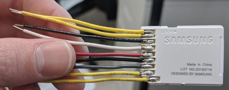
This project can be done with as little as a soldering iron, solder, an SD card adapter, and some wires. In fact, this is how I did it the first time because I had everything on hand and wasn’t sure it would work at all.

sd-adapter-with-wires_hu003643c1249d3a2482e0846e8fd03c95_425558_800x0_resize_q75_box.jpg
Wires soldered directly to SD Adapter
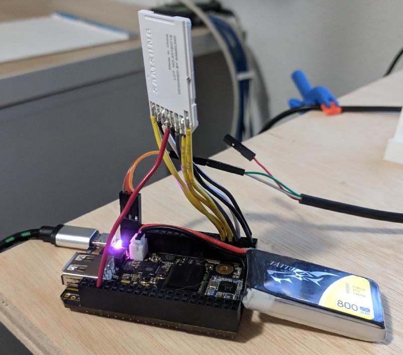
sd-adapter-kludge_hu2a10637025d80403ec56a30667f82814_439536_800x0_resize_q75_box.jpg
Ugly and cumbersome, but functional

I would recommend the following to make a nice finished project as well as making it much easier on yourself. For convenience, I’ve included links to Amazon with my Amazon Associate ID, from which I can earn a little bit for qualifying purchases. A lot of this stuff is common though and you probably have or can borrow some of it, or find it around town except for perhaps the perfboard and pin headers. Most of the stuff I have on hand anyway for various projects, so this project essentially cost me nothing but time. If you have a maker space in your town, they should have a lot of this stuff too, especially the tools.

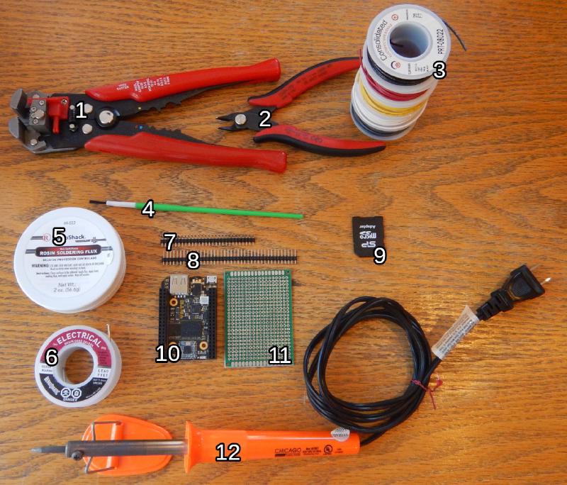
chip-sd-slot-parts-and-tools_hu0c8ad189c25ff3c3f5ad5fed29f5e260_633283_800x0_resize_q75_box.jpg
Parts and tools used to make a Micro SD card slot for your CHIP
No. Part Notes
1 Wire Strippers I really like these self-adjusting wire strippers but anything that strips insulation from wire will do just fine.
2 Flush Cutters Very useful tool to have on hand for tons of situations. I have a bunch of these.
3 Solid Wire Nice to have in several colors for color coding.
4 Brush Useful for applying flux and cleaning it up with alcohol when finished. I got a pack of cheap ones at Harbor Freight.
5 Rosin Flux If you’re having trouble soldering, more flux is usually the answer.
6 Solder Rosin core solder. Even though the solder already has flux, more still makes the job easier.
7 Right Angle Pin Header Attaches to SD card adapter.
8 Pin Header Attaches to perfboard so it can plug into CHIP. Available in a kit with right angle and others linked above.
9 SD Adapter Usually included with your Micro SD card.
10 NTC CHIP You should have this already.
11 Perfboard Great for all kinds of projects. This one is double sided and comes tinned making it easy to work with.
12 Soldering Iron Cheapo soldering iron. You should get a better one if you do this a lot. A cheap handle is fine but quality tips are worth the money. Something like the one I linked should take 900M style tips from a quality brand like Hakko. I’m using a cheap $4 iron from Harbor Freight to show it can work for you though.
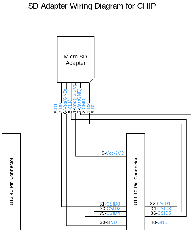
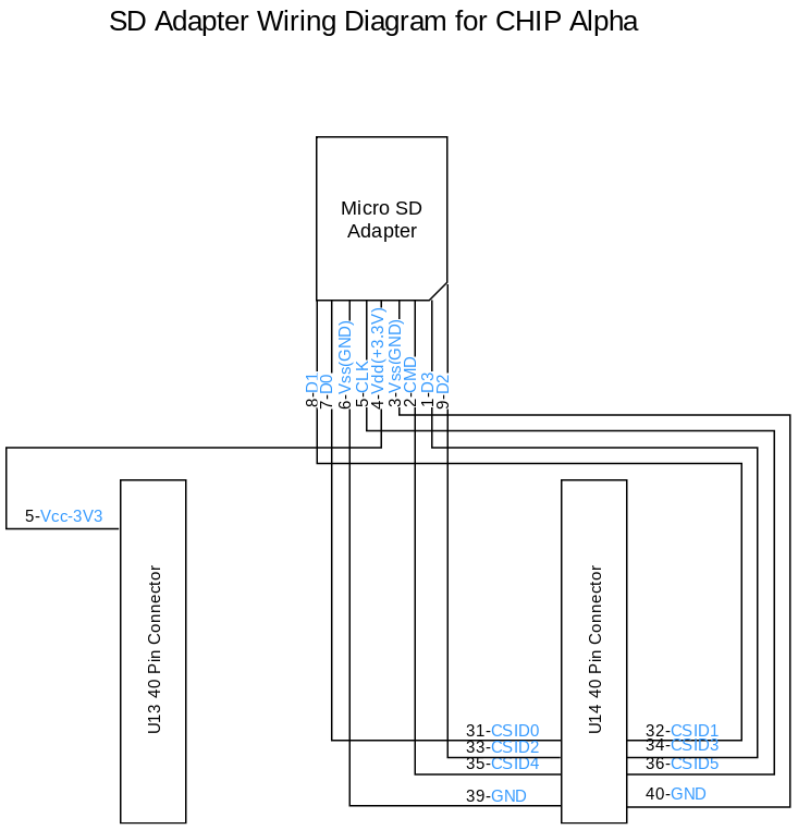
I drew some crude wiring diagrams for both the Alpha CHIP and the released version because they moved the 3V3 power supply location. You most likely have the non-Alpha version. The normal CHIP has the pin function conveniently written onto the header so it should be easy.

CHIP-SD-Adapter.png
Wiring diagram for released CHIP
CHIP-Alpha-SD-Adapter.png
Wiring Diagram for Alpha version of the NTC CHIP
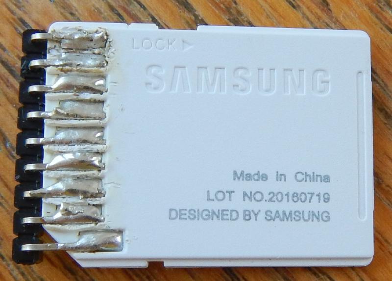
The assembly is actually fairly straightforward. Headers can be clipped apart with the flush cutters. You need to attach the longer pins of the right andgle header to the Micro SD adapter’s exposed pads. It won’t line up exactly, but it’s close enough and far easier than trying to solder on individual wires. I’d recommend a fairly large soldering tip as that will allow you to dump heat into the joint very quickly. It probably seems a bit counter intuitive, but this is what you want so you can make the solder flow and adhere well onto the pad and the pin before the heat has enough time to transfer to the surrounding area and melt the plastic. Use plenty of flux on both the adpater pads and the header pins and you should be able to get the solder to flow onto both quickly. One that is done, it can easily attach to the perfboard.

sd-adapter-with-header_hu956662ce3c1e3d7937191302776d1919_313146_800x0_resize_q75_box.jpg
SD Adapter with right angle pin header soldered onto its pads

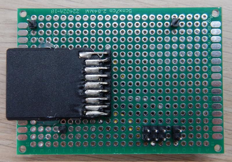
Next, you should attach some of the straight pin headers to the perfboard so that they line up with the holes on the CHIP’s headers. The short end should go to the perfboard so that the longer end can stick down into the CHIP. I found it easiest to actually stick the long end of the header into its spot on the chip, then set the perfboard on top how you want it and solder the pins in place.

SD-slot-bottom_huaf400bd49e7c3ba7fa4f9da6dd54f43f_710118_800x0_resize_q75_box.jpg
Pin headers attached to perfboard
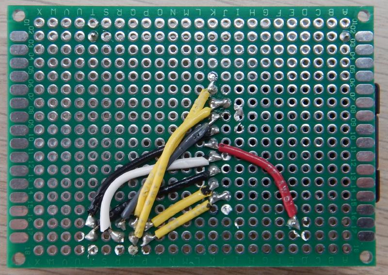
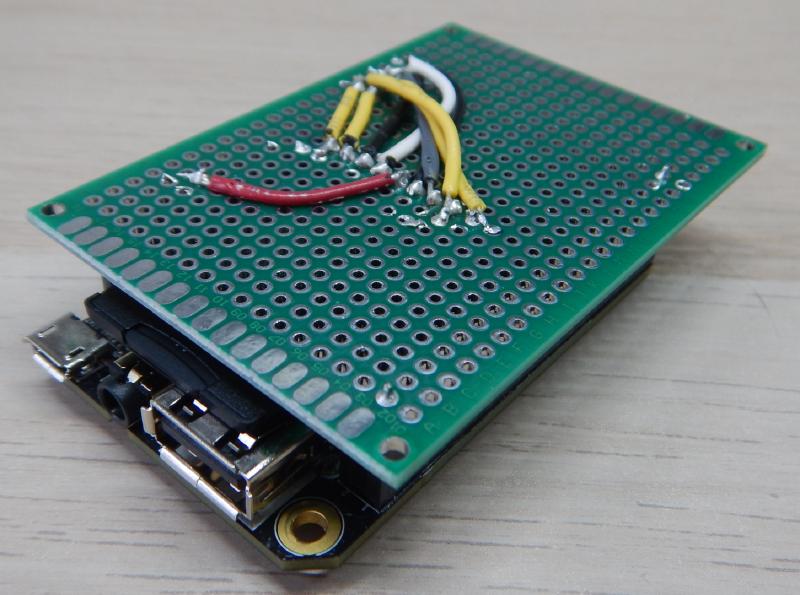
Next, you’ll need to solder wires to connect the pins from the SD Card adapter to the approriate pin on the CHIP connector. I prefer to color code mine but it doesn’t matter if you want to just use a single color. There’s probably enough solder already on the joint between the header and the perfboard to connect the wire, but feel free to add more. It’s easier to make the connection if you dip the end of the wire in some flux and tin it, that is coat it in solder on its own. It should be fairly straightforward, but be careful not to bridge any pins or short any wires together, especially on the group of six CSI pins where it gets a bit tight.

SD-slot-top_hua64ea59021b495dd1354853568419890_747297_800x0_resize_q75_box.jpg
Wires connecting SD adapter header to CHIP headers
When you’re done you may want to take a multimeter in continuity mode (beeps when the probes complete a circuit) and double check that the connections you want to be there are there and also that they don’t short out with each other. This is a pretty simple circuit so a visual inspection can go a long way also. I also added some hotglue to reinforce the adapter connection to relieve stress placed on the header when manipulating the card.

SD-slot-hotglue_hu65849b31a7eccc00f05a2f8aef391845_244500_800x0_resize_q75_box.jpg
Hot glue for stress relief
Wrapping Up
Put away your tools, that’s it for the hardware part of this project! In the next post I’ll explain how to get this to work in Linux. We need to add some information to the device tree so that Linux knows how to configure the appropriate driver and then you’ll be able to use your SD card slot. Overlaying the device tree will work on the stock NTC kernel, so if all you wanted was an SD card slot, you’re almost done.

原文地址
https://byteporter.com/ntc-chip-micro-sd-slot/